Skip to content


Engineering and procurement teams often face a difficult tradeoff between precision and production speed when sourcing custom stainless steel fabrication. Managing the alloy’s high work-hardening rates while preventing carbon steel contamination requires a disciplined, digital-first approach to ensure every component maintains its corrosion resistance in the field.
This guide details the technical workflow of modern stainless processing, from using 12,000 W fiber laser systems for thin-gauge precision to calculating K-factor ratios for accurate bending. We analyze critical cost drivers, such as why upgrading from 304 to 316L stainless typically adds a 20% to 30% material premium, and provide a framework for evaluating fabrication partners based on ISO 9001 and AWS welding standards.
The Fabrication Process Overview
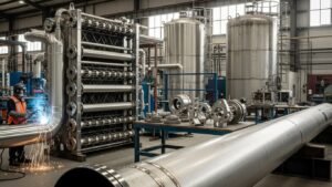
Modern stainless steel fabrication in 2026 centers on a digital-to-physical workflow. The process begins with 3D CAD modeling and CNC laser cutting of austenitic grades like 304 and 316, followed by specialized forming that accounts for high springback. Final stages involve TIG/MIG welding and chemical passivation per ASTM A380 to ensure maximum corrosion resistance.
Material Preparation and Digital Processing
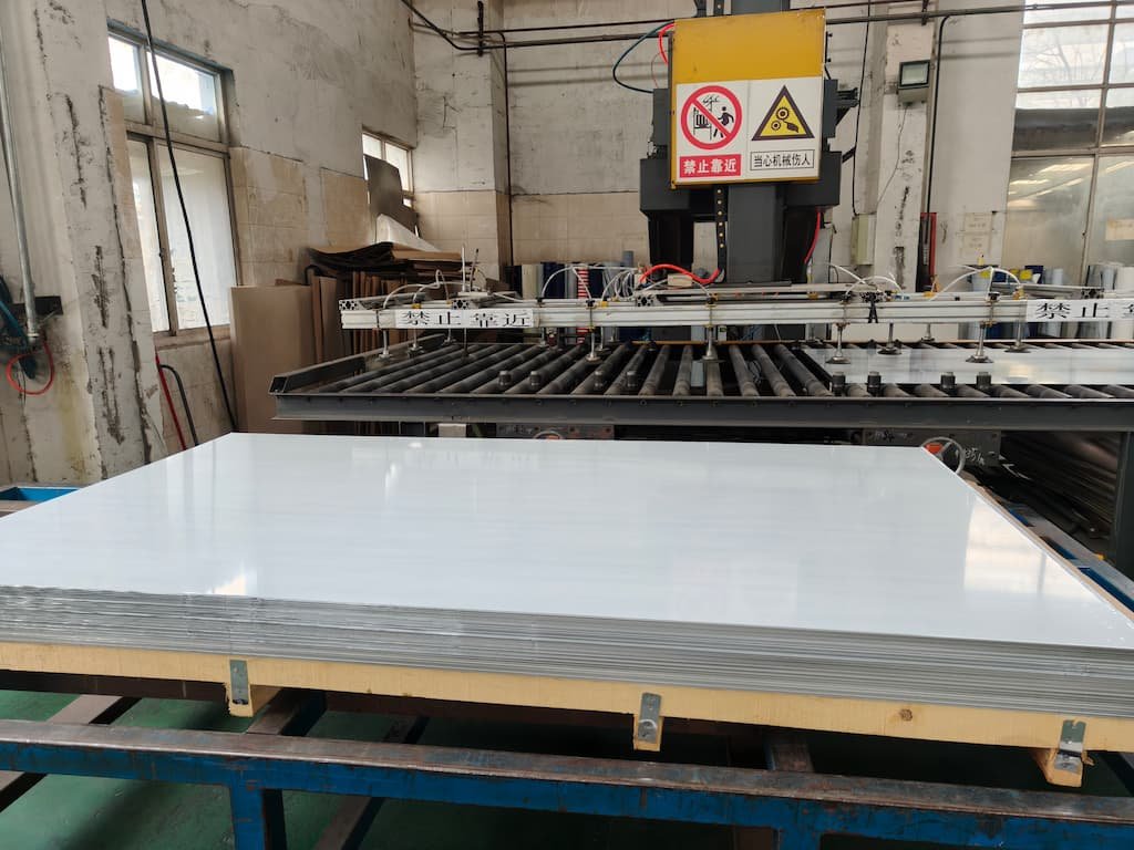
Application requirements drive the selection of specific austenitic grades like 304L or 316L. Engineers typically specify cold-rolled sheets ranging from 0.4 mm to 3.0 mm for precision components, while thicker plates exceeding 3.0 mm undergo hot-rolling. Once the material is staged, technicians upload 3D CAD models into CAM software to drive 12,000 W fiber laser systems. These high-power lasers enable high-speed cutting with tight tolerances, reducing the need for secondary edge finishing.
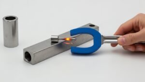
Maintaining material integrity requires strict shop floor discipline. Fabricators use dedicated stainless steel tooling for all slitting, guillotining, and bandsawing operations. Using separate tools prevents carbon steel cross-contamination, which would otherwise introduce free iron to the surface and compromise the alloy’s inherent corrosion resistance. This digital-first approach ensures that the physical component matches the engineering design with microscopic accuracy.
Forming Bending and Chemical Passivation
The mechanical shaping stage must account for the alloy’s high work-hardening rates. Press brake operators apply significant over-bend during forming to compensate for the springback levels found in stainless steel, which far exceed those of carbon steel. For thin-gauge strip or wire, cold drawing can push tensile strengths above 2000 MPa, requiring high-capacity hydraulic equipment to achieve precise radii. Following the forming stage, welders use controlled TIG or MIG techniques to assemble the components. They must strictly manage heat input to protect the heat-affected zone (HAZ) and prevent sensitization, which could lead to intergranular corrosion.
The final stages focus on restoring the material’s surface chemistry. The workshop conducts pickling and passivation in accordance with ASTM A380 standards to remove heat tint and surface impurities, allowing a robust chromium oxide film to reform. Quality assurance teams verify the entire workflow through traceability documentation and Material Test Certificates (MTC). For infrastructure projects, these steps ensure compliance with rigorous 2026 standards such as Austroads ATS 5440, providing a transparent and auditable fabrication record.
Laser Cutting vs. Waterjet: Which to Choose?
Laser cutting offers the best speed and precision for stainless steel sheets under 19 mm, reaching speeds up to 70 in/min. For plates thicker than 20 mm or projects requiring zero heat-affected zones to maintain corrosion resistance, abrasive waterjet cutting at 4,000 bar is the necessary choice.
Speed and Precision for Thin Gauge Materials
Laser cutting speeds for thin stainless range from 20 to 70 in/min, which is approximately 5 to 10 times faster than waterjet processes. Typical industrial laser tolerances reach ±0.127 mm (±0.005″) with a narrow kerf of approximately 0.64 mm. These specifications make lasers the primary tool for high-volume projects requiring fine detail and rapid turnaround.
The process works best for AISI 304/316 sheets up to 19 mm (0.75″) where high throughput and intricate geometries are required. Industrial fiber lasers use power ranges between 0.5 kW and 6 kW to ensure clean edges on standard sheet gauges, providing a balance of speed and edge quality that waterjets cannot match in thin materials.


Cold Cutting and Edge Quality for Thick Plate
Abrasive waterjets utilize 4,000 bar (60,000 psi) pressure to cut through stainless steel plates as thick as 150 mm to 300 mm. The cold-cutting nature of the waterjet prevents the formation of heat-affected zones (HAZ). This preserves the base metal’s mechanical properties and essential corrosion resistance, which is vital for components used in harsh chemical environments.
Waterjet cutting preserves the microstructure of 40 mm AISI 304 plates by avoiding the oxide inclusions and deformation common in thermal laser cutting. Technicians can also perform stack cutting of multiple material layers, maintaining accuracy through a total thickness of 100 mm to improve efficiency on heavy-duty fabrication tasks.
Bending and Forming: Calculate Your K-Factor
The K-factor is the ratio of the neutral axis position to the total material thickness, typically ranging from 0.30 to 0.50. Accurately calculating this value allows fabricators to determine the bend allowance and bend deduction, ensuring the flat-cut sheet results in precise final dimensions after forming on a press brake.
Neutral Axis and the K-Factor Ratio
The K-factor formula, K = t/T, defines the ratio where ‘t’ represents the distance from the inside surface to the neutral axis and ‘T’ is the total sheet thickness. This value helps designers locate the specific area within the metal that neither stretches nor compresses during the forming process. Because the outer fibers of the metal expand and the inner fibers compress, the neutral axis serves as the stable reference point for all flat-pattern development.
Industry standards for sheet metal typically utilize a K-factor between 0.30 and 0.50 depending on the specific material and tool setup. Sharp bends with a small inside radius relative to the material thickness often require a K-factor of approximately 0.33. When the inside bend radius is equal to or greater than the material thickness, the K-factor typically shifts toward 0.50, moving the neutral axis closer to the center of the sheet.

Bend Allowance Calculations for Precision Forming
The Bend Allowance (BA) formula is expressed as BA = (π/180) × Angle × (Inside Radius + K × Thickness). Fabricators use this calculation to find the arc length of the neutral axis. We determine the final flat length of the part by adding the lengths of the straight legs to this calculated Bend Allowance. This step is critical for ensuring that the finished part meets the design specifications after it leaves the press brake.
Material type significantly influences these variables. For a 2mm stainless steel sheet bent to 90° with a 3mm inside radius, a K-factor of 0.44 provides a reliable starting point. To account for the outside setback, we calculate the Bend Deduction (BD) as 2 × (Inside Radius + Thickness) × tan(Angle/2) – BA. This secondary calculation helps refine the flat pattern by identifying exactly how much material the bend consumes.
Maintaining high quality standards in modern fabrication requires empirical testing. Shops often bend test coupons from specific material batches to back-solve for the actual K-factor. This process accounts for machine calibration and subtle differences in material ductility, ensuring that high-precision components remain within tolerance during the production run.
High-Performance Stainless Steel Sheets for Every Industry

Welding Stainless: TIG vs. MIG
TIG and MIG processes account for 90% of stainless steel welding. TIG provides precision and superior aesthetics for thin sections using 1 amp per 0.001-inch thickness, while MIG offers higher deposition rates and speed for production. Both methods utilize low-hydrogen techniques to ensure joint integrity across grades like AISI 304.
Process Selection for Aesthetics and Production Speed
TIG (GTAW) delivers high-aesthetic welds and creates minimal heat-affected zones (HAZ) on thin sheet metal and precision joints. Fabricators prioritize this process for critical joints where appearance and tight dimensional control matter most. The fine control over the arc allows the operator to protect corrosion-sensitive surfaces and limit temper colors, which reduces the need for extensive post-weld cleaning.
MIG (GMAW) serves production environments where efficiency and volume drive the project. Utilizing pulsed power supplies increases deposition rates and helps operators weld faster or reach into complex geometries. While MIG produces more spatter and a broader HAZ than TIG, its speed makes it the standard choice for heavier sections and high-volume industrial components.
Both low-hydrogen processes effectively weld common austenitic grades such as AISI 304 and 304L. Using compatible filler materials like ER308 and ER308LSi ensures the joint maintains the corrosion resistance and mechanical integrity of the base material.
Technical Parameters for Heat and Distortion Control
Precise amperage settings prevent warping and burn-through in stainless steel. DCEN TIG procedures require approximately 1 amp per 0.001 inch (0.025 mm) of material thickness. This rule of thumb helps maintain a stable arc and manageable puddle size, keeping the heat input low enough to avoid compromising the metal’s grain structure.
Shielding gas flow and torch geometry also dictate the final weld quality. Pure argon gas flows typically range from 11–15 CFH (5.5–7 L/min) when using #4 to #6 cups for thin sections. Maintaining torch angles of 15–30° from vertical helps stabilize the puddle and limits surface discoloration. For optimal fusion, the filler rod should enter the leading edge of the puddle at an angle of approximately 15°.
Thermal management requirements change based on material thickness and grade. While sections 5 mm or thinner rarely need heat treatment, thicker sections often require preheating at 200–300 °C. Following the weld, treatments at 650–750 °C allow hydrogen to diffuse from the HAZ, which prevents cracking in susceptible grades. Proper sequencing and the use of fixtures further mitigate the risk of distortion during these thermal cycles.
Post-Fabrication Finishing (Passivation)
Passivation uses nitric or citric acid to remove free iron and surface contaminants introduced during fabrication. This process allows a 1–3 nm thick chromium-oxide layer to reform, ensuring the corrosion resistance of grades like 304 and 316 remains intact without altering part dimensions.
Restoring the Chromium-Oxide Protective Layer
Machining, grinding, and welding often leave microscopic particles of carbon steel or exogenous iron on the surface of stainless steel components. These contaminants disrupt the alloy’s natural ability to form a protective barrier, leading to localized rust or pitting. The passivation process removes these residues through controlled chemical immersion. By stripping away free iron, the treatment allows a chromium-rich passive film—typically only a few atoms thick—to reform uniformly across the part.
Unlike mechanical or abrasive finishing, chemical passivation does not change the physical dimensions or surface finish of the component. This makes it essential for high-precision parts where maintaining tight tolerances is critical. The process effectively restores the corrosion resistance of common austenitic grades like 304L and 316L, as well as precipitation-hardening alloys such as 17-4PH, without impacting the bulk mechanical properties or spring rates of the material.
Compliance Standards and Verification Testing
Fabricators rely on established industry standards to ensure the effectiveness of the passivation treatment. ASTM A967 and AMS 2700 serve as the primary specifications, defining the necessary acid concentrations, bath temperatures, and immersion times. For complex assemblies, ASTM A380 provides the framework for essential pre-treatment steps, including degreasing and the removal of weld scale. These protocols ensure the chemical bath reaches all surfaces and that the part is free of oils that could inhibit the reaction.
Quality assurance involves rigorous testing to confirm the surface has reached a passive state. Technicians use methods such as copper sulfate application, high-humidity exposure, or water immersion tests to detect any remaining free iron. Following these standardized testing procedures is mandatory for high-reliability sectors, including aerospace and medical manufacturing, where components must meet specific requirements like ASTM F86 for surgical implants.
Design for Manufacturability (DFM) Tips
Effective stainless steel DFM balances material strength with forming limits. By 2026 standards, successful fabrication relies on selecting low-carbon grades to protect weld zones and applying precise bend radii—typically 1x to 2x material thickness—to manage rapid work hardening and ensure dimensional accuracy.
| Material Category | Design Yield Strength | Key DFM Constraint |
|---|---|---|
| Austenitic (304/316) | ~240 N/mm² | High work hardening; requires low-carbon “L” grades for welding. |
| High-Strength (1.4420) | ~390 N/mm² | Allows weight reduction while maintaining ductility. |
| Ferritic (409/430) | Variable | Limit thickness to 3.2mm–3.8mm to avoid brittle transitions. |
Material Selection for Weldability and Strength
Specifying low-carbon “L” grades such as 304L (1.4307) or 316L (1.4404) for all welded sections minimizes sensitization and corrosion risks in the heat-affected zone (HAZ). Design yield strengths vary significantly by grade; standard austenitic options offer approximately 240 N/mm², while nitrogen-strengthened grades like 1.4420 reach 390 N/mm². Engineers select stabilized grades like 1.4571 for environments requiring enhanced intergranular corrosion resistance. Structural designs also factor in fire resistance, as typical austenitic grades retain substantial strength at temperatures between 600°C and 800°C.

Bending Constraints and Dimensional Tolerances
Fabricators apply a minimum inside bend radius of 1.0x material thickness (T) for standard air bending, increasing this to 2.0xT for cold-worked or harder alloys to prevent cracking. Accounting for rapid work hardening and significant springback in 300-series alloys prevents dimensional drift and micro-fractures during forming. Structural applications using ferritic grades like 409 and 430 require a maximum thickness limit of 3.8mm to avoid ductile-to-brittle transition issues. Precision designs target micron-level tolerances when fabricated shells must interface with CNC-machined components or bearing seats. Finally, eliminating stagnant liquid traps and crevice-prone joints in the design phase facilitates natural drainage and prevents localized corrosion.
Cost Drivers in Custom Fabrication
Fabrication costs depend mainly on material grade and design complexity. While 304 stainless serves as the baseline, upgrading to 316L or Duplex alloys adds 20% to 165% in material premiums. Labor rates fluctuate based on certification needs, and tightening tolerances often doubles production costs due to increased machine time and inspection requirements.
Material Selection and Labor Specialization
Material grade acts as the primary cost foundation in any stainless project. 304 stainless steel typically ranges from $2,800 to $3,200 per ton. Upgrading to 316L for enhanced chloride resistance incurs a 20–30% premium, while specialized Duplex 2205 increases material costs by 130–165%. Thickness also influences processing speed; working with 1.2 mm stainless costs 40–60% more than 0.8 mm mild steel because the material requires higher machine loads and significantly slower cutting speeds.
Human expertise and batch size shift the final quote significantly. General fabrication labor typically ranges from $45 to $85 per hour. Certified processes for critical industrial applications command higher rates between $125 and $175 per hour. For prototypes or single-piece orders, costs frequently exceed $75 per pound because the shop must amortize setup, programming, and fixturing expenses over very few units.
Tolerance Precision and Design Complexity
Engineering requirements and part geometry dictate manufacturing efficiency. Moving from a standard ±0.030-inch shop tolerance to a precision ±0.005-inch requirement typically doubles the machining cost. Ultra-precision demands of ±0.001 inch can drive costs up by 400–600% through the necessity for specialized metrology and reduced feed rates. Relaxing tolerances where function allows remains one of the most effective ways to control production expenses.
Geometric complexity determines the finished price per pound. Simple fabricated parts generally range from $8 to $15 per pound, whereas complex precision assemblies cost between $25 and $45 per pound. Data indicates that incomplete initial specifications cause 60–70% of budget overruns in custom projects. Investing in upfront value engineering and clear Design for Manufacturability (DFM) reviews often reduces total project costs by 15–35% by simplifying bend sequences and consolidating parts.
Choosing a Fabrication Partner
A reliable partner must maintain ISO 9001 certification and adhere to AWS or ASME welding standards to ensure precision. Evaluate their CNC equipment capabilities, Design for Manufacturability (DFM) support, and willingness to provide Material Test Certificates (MTC) and third-party inspections for full traceability.
| Evaluation Criteria | Standard/Requirement | Project Impact |
|---|---|---|
| Quality Management | ISO 9001:2015 | Ensures consistent production workflows and traceability. |
| Welding Integrity | AWS / ASME Standards | Guarantees structural safety and corrosion resistance. |
| Precision Machining | CNC Laser & Brakes | Maintains tight tolerances for complex component designs. |
| Material Validation | MTC & 3rd Party Inspection | Confirms chemical composition and grade compliance. |
Technical Competencies and Industry Certifications
Selecting a partner for stainless steel fabrication requires a systematic review of their technical infrastructure and regulatory compliance. Procurement teams verify ISO 9001:2015 certification to confirm that a supplier maintains established quality management systems. These standards provide a baseline for consistency across large production batches. Welding teams must follow AWS or ASME protocols to ensure the structural integrity of components, especially when working with thin-gauge stainless steel that is prone to warping under high heat.
Advanced facilities utilize CNC-controlled equipment, including multi-axis press brakes and fiber laser cutters, to achieve high precision and repeatable results. This technology allows for tolerances that manual processes cannot match. Expertise in specialized TIG and MIG welding plays a vital role in managing the heat-affected zone. Proper thermal management helps maintain the corrosion-resistant properties of the alloy, ensuring the longevity of the finished product in demanding environments.
Verification Protocols and Engineering Support
Engineering support reduces project risks through comprehensive Design for Manufacturability (DFM) reviews. During this phase, engineers examine CAD and DXF files to suggest modifications that simplify production without compromising performance. This proactive analysis prevents costly errors and material waste during the fabrication cycle. To ensure full traceability, suppliers must provide Material Test Certificates (MTC) with every order to confirm the chemical composition and grade of the raw steel used.
Reliable fabricators often facilitate third-party inspections through agencies such as SGS or BV to validate that products meet specific project requirements before packaging. This verification step provides an objective assessment of quality and dimensional accuracy. Additionally, providers with experience in global logistics and Incoterms ensure that components arrive on-site without customs delays or unexpected shipping costs. Effective communication regarding lead times and material availability helps maintain project schedules and production goals.
Final Thoughts
Successful stainless steel projects demand a mix of digital accuracy and metallurgical knowledge. Shops that prioritize material discipline prevent common issues like surface rust and mechanical failure. Matching specific grades to the right cutting and welding techniques keeps components within tolerance and preserves the alloy’s natural durability over decades of service.
Smart designs use low-carbon grades and appropriate bend radii to handle the physical limits of the metal. These choices reduce scrap and speed up production without sacrificing structural strength. Working with a certified partner who provides full material traceability secures the supply chain for critical infrastructure and high-reliability industrial applications.
Frequently Asked Questions
What is the standard tolerance for industrial laser cutting?
Industrial sheet metal laser cutting typically maintains a standard tolerance of ±0.005 inches (±0.13 mm). Most fabrication workflows in 2026 utilize a default design rule of ±0.10 mm for precision profiles to ensure consistent fitment in complex assemblies.
Can you weld 304 stainless steel to 316 stainless steel?
Yes, you can weld 304 to 316 stainless steel using standard austenitic filler metals and procedures following AWS D1.6 guidelines. Using low-carbon variants like 304L and 316L (0.03% maximum carbon) helps minimize carbide precipitation and maintains optimal corrosion resistance at the joint.
How do fabricators remove weld discoloration and heat tint?
Technicians remove heat tint using 20–25% nitric acid solutions for 10–30 minutes, mechanical abrasion with 40–120 grit flap discs, or electrolytic cleaning at 5–20V DC. These steps are followed by passivation according to ASTM A967 standards to restore the surface integrity.
Which file formats are necessary for custom fabrication orders?
Custom fabrication projects require digital files like DXF, DWG, or IGES for 2D profiles. STEP (.stp) files serve as the ISO-standard format for 3D interoperability, providing necessary data for CNC bending and material thickness calculations.
Why is stainless steel more difficult to machine than carbon steel?
Stainless steel grades like 304 and 316 have machinability ratings of roughly 40–65% compared to free-cutting carbon steel (AISI B1112). This lower rating means they require approximately 1.5–2.5 times lower cutting speeds and cause faster tool wear due to their high work-hardening characteristics.
What is passivation and is it mandatory for all projects?
Passivation is a chemical treatment per ASTM A967 that removes free iron to restore the chromium oxide passive layer, which is only 1–3 nanometers thick. While it is mandatory for medical, aerospace, and sanitary applications, it is also recommended for any welded or machined parts to prevent premature surface oxidation.