Skip to content


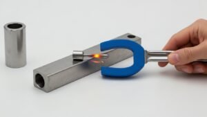
In high-precision CNC manufacturing, the margin between a profitable run and a bin full of scrapped parts often comes down to managing the notorious work-hardening rates of austenitic alloys. While stainless steel offers indispensable durability, its low thermal conductivity can concentrate heat at the cutting edge and accelerate tool wear by up to 40%, directly impacting your bottom line and production throughput.
This guide provides a technical roadmap for optimizing your operations, covering everything from the 2-3% molybdenum addition that distinguishes Grade 316 to the specific SFM parameters (100–350 for milling) required for stable cycles. We will analyze the machinability trade-offs between 304 and 316, recommend PVD coating strategies to extend tool life, and detail the precise feeds and speeds necessary to achieve industrial tolerances as tight as ±0.005 mm.
Understanding Stainless Steel 304 vs. 316
Grade 304 is an 18/8 chromium-nickel steel offering excellent machinability and cost-efficiency for general use, while Grade 316 includes 2-3% molybdenum to provide superior corrosion resistance against chlorides and pitting. Choosing between them depends on whether you prioritize production speed (304) or durability in harsh chemical or marine environments (316).
Chemical Composition and Corrosion Resistance
Grade 304 (A2 Stainless) consists of approximately 18% chromium and 8% nickel, providing strong general-purpose corrosion resistance and excellent formability. In contrast, Grade 316 (A4 Stainless) features a similar base of 16-18% chromium and 10-14% nickel, but its defining characteristic is the addition of 2-3% molybdenum. This specific chemical addition dramatically alters its performance in aggressive environments.
The molybdenum in 316 specifically enhances resistance to pitting and crevice corrosion in chloride-rich environments, such as marine settings or chemical processing plants. While 304 remains the industry benchmark for food processing and architectural applications due to its cost-effectiveness, it remains susceptible to pitting in high-saline conditions where Grade 316 thrives.
CNC Machinability and Industrial Production Impact
In terms of machinability, Grade 304 offers a distinct advantage over 316. Grade 316 is harder and possesses a significantly higher work-hardening rate, which can lead to increased tool wear and downtime if not managed correctly. Production data indicates that optimizing for 304 can increase output from 1,000 pieces to 3,000 pieces per 8-hour shift, effectively reducing rejection rates from 30% to less than 1% through more stable machining cycles.
Navigating the challenges of machining 316 requires adjusted strategies, including slower feeds, sharper tools, and positive rake inserts to mitigate the material’s tendency to “gum” and cause premature failure. Because Grade 316 typically carries a 30% higher material cost and requires more rigid setups, 304 remains the preferred selection for high-volume structural components where extreme chemical or marine corrosion is not a decisive factor.
Why Stainless Steel is Challenging to Machine
Machining stainless steel is challenging due to low thermal conductivity, which concentrates heat at the tool edge, and high work-hardening rates in austenitic grades. These factors increase tool wear by up to 40% and necessitate specific speed adjustments (SFM 100-350) to prevent material deformation.
Metallurgical Challenges: Heat Retention and Work Hardening
The primary hurdle in processing stainless steel is its low thermal conductivity. Unlike standard carbon steels, where heat is efficiently dissipated through the metal chips, stainless steel causes thermal energy to concentrate at the cutting zone. This localized heat buildup can accelerate tool and insert wear by 20% to 40%, necessitating advanced coolant strategies to prevent the cutting edge from softening or deforming under load.
Austenitic grades, most notably the 304 and 316 series, exhibit rapid work hardening during the machining process. As the tool moves through the material, the mechanical action increases the hardness of the shear zone. This transition requires significantly higher cutting forces for subsequent passes and demands a constant feed rate to ensure the tool tip remains beneath the work-hardened layer of the previous cut.
Furthermore, the high material toughness of stainless alloys leads to the formation of long, “gummy” chips. These chips are difficult to break and often lead to built-up edge (BUE) formation, where material adheres to the tool tip. This adhesion can degrade surface finish accuracy and cause catastrophic tool failure if the adhered material pulls away fragments of the tool’s carbide substrate.
Operational Impact on Tooling and Precision Parameters
Martensitic and precipitation-hardening grades, such as 17-4 PH, present additional challenges due to the presence of abrasive chromium carbides. These micro-constituents increase cutting forces and accelerate tool erosion. Machinists must balance the high strength and fracture toughness of these AISI stainless alloys by using specialized geometries that reduce friction and heat generation during the chip-forming process.
To mitigate these effects, strict adherence to specific running parameters is required. Surface Feet per Minute (SFM) must generally be maintained between 100 and 350 depending on the specific grade and hardness. Additionally, chip loads must be precisely managed, often ranging from 0.0005” for a 1/8” end mill to 0.006” for a 1” tool, to ensure that the material is being cut efficiently rather than rubbed, which would exacerbate thermal issues.
Precision requirements in stainless machining often demand the use of specialized carbide tools with advanced coatings like Titanium Aluminum Nitride (TiAlN) or Titanium Carbonitride (TiCN). These coatings provide the necessary heat resistance and lubricity to handle the material’s high tensile strength. By utilizing these tools alongside rigid machine setups, manufacturers can achieve tight CNC precision tolerances of ±0.005 mm and surface finishes as fine as Ra 0.1 μm for demanding 316L applications.
Recommended Speeds and Feeds for Stainless Steel
Machining stainless steel requires lower surface speeds (100–350 SFM for milling, up to 710 SFM for turning) compared to carbon steel, paired with aggressive feed rates to stay below the work-hardened layer. Maintaining a chip load above 0.001 inches and using specific carbide grades like ISO CC-3 or CM10 are essential for tool longevity.
| Machining Operation | Surface Speed (SFM) | Feed Rate / Chip Load |
|---|---|---|
| Turning (Roughing – Carbide) | 520 – 710 SFM | 0.02 – 0.06 in/rev (ipr) |
| Milling (CNC End Mill) | 100 – 350 SFM | 0.0005 – 0.006 in/tooth |
| Drilling (304 Stainless) | 260 – 340 SFM | 0.001 in/tooth (Minimum) |
| Grooving & Parting | 210 – 430 SFM | 0.004 – 0.01 in/rev (Finishing) |
Core Principles of Stainless Machining Parameters
The primary challenge when machining austenitic grades like 304 and 316/316L is their inherent tendency toward strain-hardening. To manage this, machining parameters must be set so that the cutting edge penetrates deeply enough to stay ahead of the work-hardened layer created by the previous pass. Failure to maintain this depth leads to rapid tool wear as the insert rubs against a surface that has become significantly harder than the base material.
University of Florida engineering guidelines emphasize that chip loads must never drop below 0.001 inches per tooth for tools like annular cutters. This minimum threshold ensures the tool is actively cutting rather than burnishing the metal. Modern carbide selection is equally critical; utilizing ISO CC-3/CM10 or CC-7/CP10 grades allows operators to push surface speeds up to 875 SFM in ideal conditions, whereas traditional High-Speed Steel (HSS) is generally limited to a conservative 100 SFM.
Effective thermal management is the final pillar of stainless machining. Because stainless alloys have low thermal conductivity, heat remains concentrated at the cutting edge. High-value machining data assumes a rigid setup with short tool overhang and consistent, high-pressure coolant flow to evacuate heat and prevent localized hardening of the workpiece.
Technical Data for Turning, Milling, and Drilling
For stable turning operations on AISI 304 and 316, surface speeds typically range between 160–215 m/min (520–710 SFM). Feed rates should be adjusted based on the phase of the operation: roughing passes perform best at 0.05–0.3 mm/rev, while finishing passes require a tighter range of 0.02–0.1 mm/rev to achieve specified surface textures without inducing surface stress.
In CNC milling applications, Harvey Performance data suggests a wide SFM band of 100–350 depending on tool diameter and substrate. Chip loads must scale with the tool size, moving from 0.0005 in/tooth for a 1/8″ end mill up to 0.006 in/tooth for a 1″ end mill. For 304-specific milling with optimal rigidity, speeds can be safely maintained between 330 and 440 SFM.
Holemaking requires specialized adjustments, particularly for deep-hole drilling. Allied Machine & Engineering recommends applying a 0.80 scaling factor to both SFM and Inches Per Revolution (IPR) when drilling at depths reaching 7xD. Furthermore, specialty operations like parting and grooving on 304 stainless should be run at 210–280 SFM and 310–430 SFM respectively to ensure clean chip evacuation and tool stability.
Maximize Performance with Premium Stainless Steel Sheets

Selecting the Best Tooling and Coatings for 304/316
Machining 304 and 316 stainless steel requires carbide tooling equipped with PVD coatings like TiAlN or TiCN, utilizing positive rake angles (5-15°) and relief angles (10-12°) to counteract rapid work hardening. While 304 offers a machinability rating of 45-55%, the molybdenum content in 316 drops its rating to 35-45%, necessitating a 10-20% reduction in feed rates and specialized geometries to manage higher cutting temperatures and tougher chip formation.
| Machining Parameter | Grade 304 Specification | Grade 316 Specification |
|---|---|---|
| Machinability Rating (AISI) | 45-55% (70 Rating) | 35-45% (60 Rating) |
| Turning Speed (SFM) | 250 – 350 SFM | 200 – 300 SFM |
| Milling Speed (SFM) | 300 – 400 SFM | 250 – 350 SFM |
| Drilling Speed (SFM) | 70 – 100 SFM | 50 – 80 SFM |
| Relative Tool Life | 1.2x Baseline | 1.0x Baseline (Reference) |
Optimal Tool Geometry and Material Selection
To achieve precision in austenitic stainless steels, tooling must prioritize sharp edges and high lubricity. Carbide inserts are the industry standard, but they must be paired with specific geometries: positive rake angles ranging from 5° to 15° and relief angles between 10° and 12°. These angles reduce the cutting force and minimize the friction that leads to work hardening. For high-heat operations where vibration is a concern, cobalt high-speed steel (HSS) tools offer a secondary option, though they lack the wear resistance of coated carbides in high-volume production environments.
Coating Technologies for Heat and Wear Resistance
Physical Vapor Deposition (PVD) coatings are essential for extending tool life by up to 40% when machining 304 and 316. PVD TiCN (Titanium Carbonitride) is particularly effective for high-speed turning, with some grades supporting speeds up to 1000 SFM. Alternatively, PVD TiAlN (Titanium Aluminum Nitride) provides superior thermal protection, forming an aluminum oxide layer at the cutting edge to insulate the tool substrate. This is critical for 316L, which exhibits higher initial hardness and requires premium grades like KC5010 to maintain edge integrity during finish machining.
Managing Feed Rates and Work Hardening
The primary challenge when transitioning from 304 to 316 is the latter’s toughness and tendency to gall. Operators should implement a 10-20% reduction in feed rates for 316 to accommodate the tougher chips and higher horsepower requirements. Maintaining a consistent chip load, generally between 0.0005 and 0.006 IPR, is vital to stay ahead of the work-hardened layer. Furthermore, the use of round insert geometries can help distribute heat more evenly across the cutting edge, preventing localized burnout and ensuring that 304 maintains its 1.2x tool life advantage over 316 in high-production cycles.
Strategies for Extending Tool Life in High-Volume Runs
Extending tool life in high-volume 316L runs requires a combination of coated carbide tooling (ISO 513 group K/M), high-speed machining (HSM) speeds of 150–300 m/min, and constant-engagement toolpaths like trochoidal milling. These methods, paired with rigid fixturing and optimized chip evacuation, mitigate the severe work-hardening and thermal constraints of stainless steel.
Tool Material Selection and Thermal Management
The selection of tool materials for high-volume 316L stainless steel machining is dictated by the alloy’s low thermal conductivity and aggressive work-hardening. To combat crater and flank wear, manufacturers utilize coated carbide grades within the ISO 513 group K and M designations. These substrates provide the necessary toughness and wear resistance required to withstand the high mechanical loads found in continuous production environments.
To further enhance performance, multilayer coatings such as TiAlN or AlTiN are applied per ISO standards to maintain hot hardness. These coatings serve as a critical tribological barrier during high-speed machining (HSM) operations, reducing the thermal flux into the tool substrate. By mitigating heat transfer, these coatings prevent premature thermal softening and edge failure that typically occur when machining austenitic alloys at elevated speeds.
Effective thermal management also relies on strategic coolant delivery and specialized flute geometries. Optimized designs prevent the packing of chips within the gullets, which is essential for avoiding the recutting of work-hardened 316L fragments. This systematic approach to chip evacuation significantly reduces abrasive wear on the cutting edges and maintains the integrity of the tool’s geometry throughout its service life.
Dynamic Toolpaths and Mechanical Stability Parameters
Maintaining mechanical stability is paramount for extending tool life in difficult-to-machine alloys. Carbide cutting speeds should be sustained between 150–300 m/min when utilizing dynamic toolpaths, such as trochoidal or constant-engagement milling. These strategies stabilize the engagement angle and maintain chip thickness within a narrow, optimized band, preventing the force spikes that typically drive micro-chipping during conventional slotting.
Vibration and chatter are primary drivers of edge micro-chipping and catastrophic tool failure in stainless steel applications. To suppress these phenomena, technical protocols require a reduction in gauge length—minimizing tool overhang from the holder—and an improvement in fixturing rigidity. Stable clamping conditions ensure that the tool-workpiece interface remains consistent, preventing the erratic loading that accelerates flank wear.
Data-driven maintenance plays a crucial role in maximizing resource efficiency in modern CNC operations. Implementing a cutting-tool resource management framework allows for the precise tracking of expected tool life in minutes and utilized life as a percentage. This enables engineers to establish reliable tool-change intervals based on actual performance metrics, ensuring maximum productivity and consistent surface finish quality in high-volume 316L production runs.
Common Machining Mistakes to Avoid
Common machining mistakes stem from geometric, thermal, and setup-induced errors that compromise workpiece integrity. Significant issues include thermal expansion of ball screws causing errors up to 100 µm/m and improper tool alignment. Avoiding these requires strict adherence to ISO 230-1 standards and the implementation of closed-loop linear encoders to maintain tolerances within ±28 µm.
Dimensional Defects and Setup Inaccuracies
Dimensional inaccuracies in CNC machining often manifest as workpieces that are under- or over-sized, or exhibit ovality in internal and external diameters. These defects are frequently the result of fundamental setup errors, such as centerline or angular misalignment of the tool, and improper clamping techniques that induce unwanted vibrations. Such instability not only compromises the surface finish with visible tool marks and chattering but also significantly accelerates tool wear and premature failure.
Operational failures, including incorrect coordinate settings and improper tool offsets, represent a major source of material waste and production downtime. When tool offsets are inaccurately calculated or entered, it can lead to batch-wide failures where every component produced falls outside the required tolerance zone. Furthermore, selecting the wrong technology or tool geometry for specific features can result in form errors, such as poor flatness or improper chamfers, which negate the precision of the entire fabrication process.
Technical Error Sources and ISO 230-1 Standards
Precision is heavily influenced by thermal and kinematic factors that may not be immediately visible. Recirculating ball screws are particularly susceptible to thermal expansion due to high feed rates and friction forces; they can expand by as much as 100 µm/m within just 20 minutes of operation. This expansion introduces significant position errors that shift dimensions mid-process. Without secondary feedback systems like linear encoders, residual errors from drive deformation and reversal kinematics can contribute an additional 50 µm/m in inaccuracies.
To mitigate these risks, high-precision operations rely on the ISO 230-1 standard, which classifies 21 specific error components in a 3-axis machine, including 18 geometric/kinematic component errors and 3 location errors. Utilizing a closed-loop system with linear encoders provides a distinct advantage in maintaining these standards. Empirical data shows that while a semi-closed-loop system may allow contouring deviations of up to 44 µm, a fully closed-loop configuration can tighten those deviations to ±28 µm, ensuring consistent accuracy even under varying thermal loads and high-speed conditions.
Partnering with a Precision OEM for Stainless Steel Machining
Partnering with a precision OEM ensures material integrity by using digitally-driven CAD-to-CAM workflows that mitigate work hardening in austenitic grades. By leveraging advanced 12,000W fiber lasers and multi-axis CNC equipment, OEMs deliver tolerances as tight as ±0.002″, ensuring repeatability and scalability for high-volume industrial applications.
Mitigating Material Challenges via Digitally-Driven Workflows
Modern precision OEMs utilize direct CAD-to-CAM workflows paired with 12,000W Trumpf FiberLasers to eliminate manual entry errors and ensure micron-level precision. This digital integration allows for seamless transitions from design to production, maintaining the integrity of complex geometries across high-volume production runs. By leveraging 5-axis and 6-axis vertical/horizontal milling, these specialized facilities can execute single-operation cuts that optimize tool life and reduce the risk of dimensional drift.
To combat physical material limitations, such as work hardening in austenitic grades like 304, 316, and 316L, OEMs implement rigid setups and high-pressure coolant systems. These measures are critical for maintaining the material’s crystalline structure during high-speed operations, preventing the rapid strengthening that typically causes springback or micro-fractures. Furthermore, the implementation of ISO 9001:2015 quality management systems guarantees that these optimized parameters are consistently applied, ensuring repeatability whether for a prototype or a million-piece order.
Technical Capabilities for High-Precision Applications
Specialized OEMs achieve tight dimensional tolerances ranging from ±0.002″ to ±0.005″ for standard features, with the capacity to reach micron-level accuracy for critical interfaces. Their equipment versatility includes Swiss turning for small-diameter bars up to 7/8″ and heavy-duty chucking for parts reaching up to 20″ in diameter. This range of capability is essential for diverse industrial sectors, from the delicate components required in medical instrumentation to the robust manifolds used in HVAC and pressure systems.
Material expertise is a cornerstone of the OEM partnership, particularly when machining specialized grades. This includes sulfur-enhanced 1.4305 (303) for maximized CNC efficiency and 316L for environments requiring superior corrosion resistance. Every production run undergoes rigorous verification through Coordinate Measuring Machine (CMM) inspections. To ensure total transparency and compliance with industry standards, OEMs provide full Material Test Certificates (MTC) for every delivery, confirming that both chemical composition and dimensional accuracy meet the highest technical benchmarks.
Final Thoughts
Successfully machining stainless steel 304 and 316 requires a strategic balance between aggressive material removal and strict thermal management. While 304 remains the industry standard for high-volume efficiency and cost-effectiveness, the molybdenum-enhanced chemistry of 316 demands a more refined approach with specialized tooling and reduced feed rates to combat its superior toughness and rapid work-hardening tendencies. Ultimately, the choice between these grades dictates not only the component’s performance in corrosive environments but also the entire operational logic of the CNC production cycle.
To achieve consistent precision and maximize tool life in industrial runs, manufacturers must leverage advanced PVD coating technologies and dynamic toolpaths that mitigate the inherent metallurgical challenges of austenitic alloys. Partnering with a precision OEM that integrates digitally-driven CAD-to-CAM workflows with rigid, multi-axis machining platforms ensures that tight tolerances are maintained despite the high mechanical loads and thermal flux typical of stainless fabrication. By adhering to these data-driven parameters and ISO-certified quality standards, engineers can secure a reliable, scalable production process for even the most demanding high-performance applications.
Frequently Asked Questions
Why is stainless steel considered difficult to drill compared to carbon steel?
Austenitic grades like 304 and 316 possess high tensile strength and a strong tendency to work harden. If the drill rubs rather than cuts, it generates heat and rapidly hardens the material. To prevent this, HSS drills must run at low speeds (30–40 SFM) with aggressive feeds to ensure constant material removal.
What are the recommended speeds and feeds for milling 304 stainless?
For carbide end mills, roughing 304 stainless typically requires speeds between 100–200 SFM, while finishing can reach 300–350 SFM. Chip loads should be carefully managed, ranging from 0.0005″ per tooth for 1/8″ tools up to 0.006″ per tooth for 1″ tools.
Do I strictly need carbide tooling for stainless steel projects?
While HSS is acceptable for low-volume manual work, carbide is the industry standard for production. Carbide tools can run 3–5x faster than HSS (e.g., 200–350 SFM vs. 70–100 SFM) and maintain the ‘hot-hardness’ required to withstand the abrasive nature of stainless and nickel alloys.
How can I prevent work hardening during the machining process?
To stop work hardening, you must use sharp, positive-rake tooling and maintain a minimum chip load of at least 0.05 mm/tooth. Avoid ‘spring passes,’ dwelling, or light skim cuts, as these cause the tool to rub against the surface rather than penetrate the material.
What type of coolant concentration is best for machining 316L?
An industry-standard high-pressure oil/water emulsion is recommended, specifically with an 8-9% oil content—nearly double the 3-4% used for standard machining. High-pressure delivery (500-1000 PSI) is ideal for chip evacuation and heat management in deep cavities.
What is the best approach for tapping stainless steel holes?
Use cobalt or carbide taps and drill for a 55–65% thread depth rather than the standard 75% to reduce torque. Tapping should be performed at 30–50% of the speed used for mild steel (approx. 5–10 SFM) using high-feed, no-dwell cycles and high-lubricity tapping paste.